Multiaxial loading and its effects
This is an excerpt from Biomechanics of Injury-3rd Edition by Ronald F Zernicke,Steven P Broglio,William C Whiting.
We have so far considered only the simple case of uniaxial loading. In most real-life situations, however, the forces applied to a body are multidimensional, and hence an understanding of multiaxial loading and its effects is essential. An analysis of multiaxial loading uses the same stress and strain concepts just discussed and extends them into two- and three-dimensional space. Although the biaxial and triaxial responses are illustrated for tensile loading only, the concepts are equally applicable to compressive loading and to force vectors with reversed orientation. The following formulations are for linearly elastic materials.
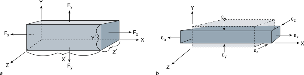
Biaxial (Two-Dimensional) Loading Responses Consider a three-dimensional body (figure 3.29) with sides of length X′, Y′, and Z′ that is subjected to axial forces Fx and Fy. The stresses produced in the X and Y directions are as follows:

The X-direction stress (σx) will, according to Poisson’s effect, cause deformation in all three directions. Elongation in the X direction and contraction in the Y and Z directions are shown in figure 3.29b. By applying equations 3.34 and 3.35, we obtain X- and Y-direction strains attributable to σx:

We similarly obtain Y- and X-direction strains attributable to σy:

To obtain the combined effect of σx and σy, we add the strain effects just calculated. The net strains in the X and Y directions are then

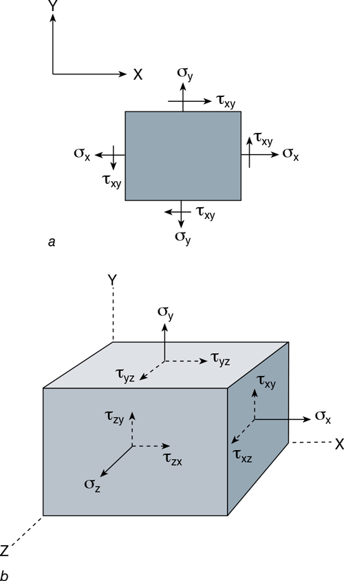
We have presented two normal stresses, σx and σy. As previously described, a tangential, or shear, stress (τ) is also created. In the case of biaxial loading, shear stress (τxy) is created as shown in figure 3.30a.

Triaxial (Three-Dimensional) Loading Responses The addition of a third axial force in the Z direction complicates the conceptual model only slightly, whereas the mathematical aspects of the model become quite involved. Focusing on the conceptual application (figure 3.31), we now have
- Fx, which creates σx = Fx/(y′ · z′) and produces elongation in the X direction and contraction in the Y and Z directions
- Fy, which creates σy = Fy/(x′ · z′) and produces elongation in the Y direction and contraction in the X and Z directions
-
Fz, which creates σz = Fz/(x′ · y′) and produces elongation in the Z direction and contraction in the X and Y directions
The equations for resultant strains seen in triaxial loading are

The shear stresses (τxy, τyz, τzx) produced in triaxial loading are shown in figure 3.30b.
More Excerpts From Biomechanics of Injury-3rd EditionSHOP

Get the latest insights with regular newsletters, plus periodic product information and special insider offers.
JOIN NOW